Automotive Digital Boost Gauge
Programmed and assembled a digital boost gauge for my car, using an esp32 microcontroller and Arduino components
Timeline
Aug 2025 - Oct 2025
Tools & Software
Arduino IDE, Circuits, C++
Engineering Focus
Mechatronics
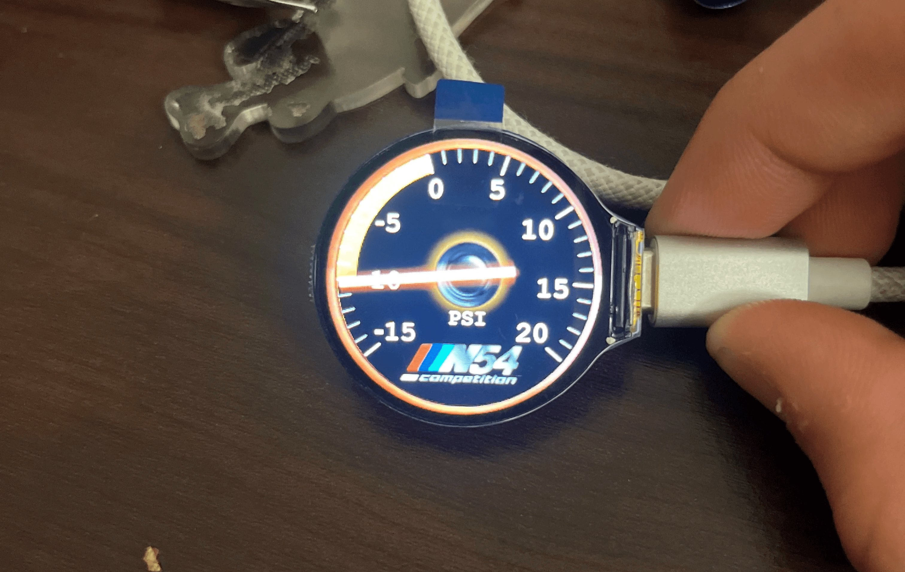
Project Overview
The goal of this project was to create a custom digital boost gauge to monitor the boost (from the turbo) in my car.
The way I went about it was connecting a pressure sensor to the esp32 microcontroller, and depending on the pressure reading I would display the corresponding image. I connected the other side of the pressure sensor to a line that was tapped into the intake manifold, from which I would read the boost.


Design and Testing
I started off this in photoshop, and created a drawing of the digital display. I then created an image for each of the pressure readings (from -15 to 20 psig -> 35 images total). I then went into Arduino IDE, converted all my images from png to byte arrays, and wrote a simple script in C++ that would smoothly change the images depending on the pressure readings from the sensor. I would test this system with a syringe first, to check if the boost gauge changes readings with different pressures before integrating it into the car. After I ensured everything was working as I intended, I finally put this assembly into my car, and dialed my boost gauge readings with trusted MHD readings while the car was running. I would do a couple of runs, see the true boost value, and change my code of the gauge so it reflects the accurate value.
One of the challenges I encountered was not having enough storage to store all 35 png images in the esp32. The controller has about 4mb of flash storage, of which 1.3mb is actual usable, and my images were at around 3mb originally. I therefore had to increase usable flash through partition settings, and optimize my images and code to fit all the data into the controller.

